Alumina Ceramic substrates
Alumina ceramic substrates are a type of ceramic substrate that is made of aluminum oxide. They are a high-performance material with excellent electrical, thermal, and mechanical properties. Alumina ceramic substrates are used in a variety of applications, including printed circuit boards, power devices, and sensors.
Ceramic Substrate Manufacturing Company
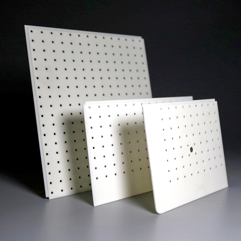
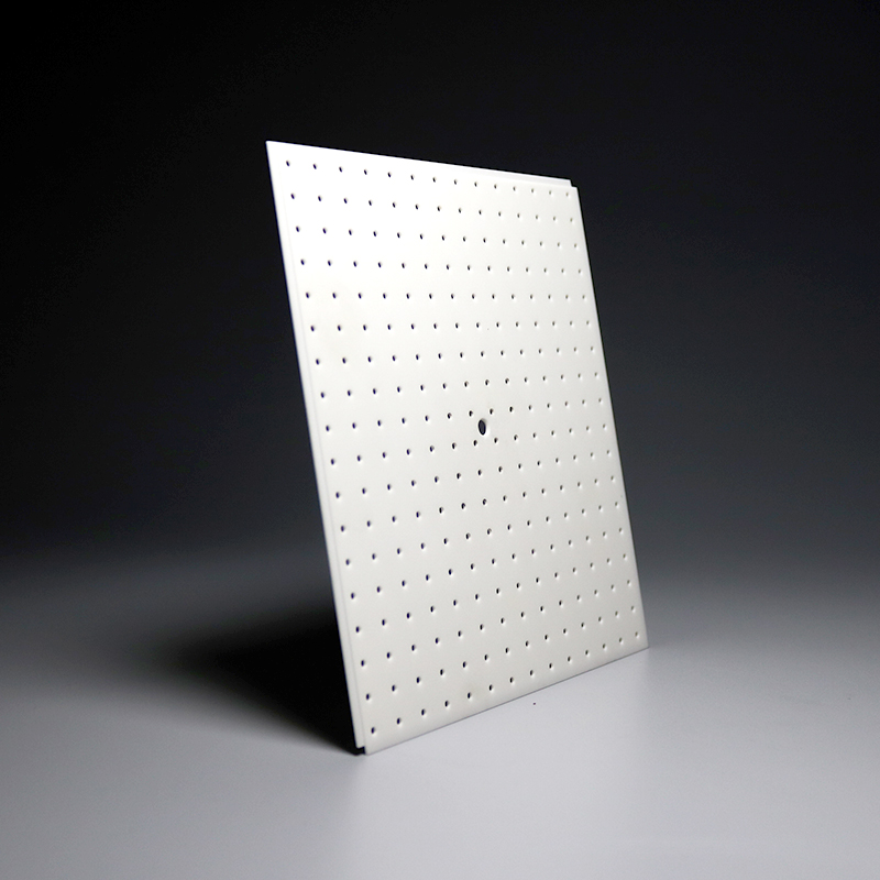
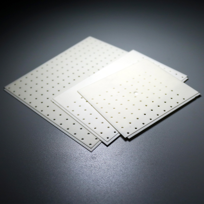
Loongeram provides a variety of alumina ceramic substrates of different purity, which are produced by tape casting and mold pressing. It mainly has the characteristics of superior comprehensive performance, good thickness uniformity and high density. Various shapes can be customized according to customer needs through laser cutting and other processes, and surface metallization can be performed.
Ceramic Substrate Manufacturing Company
Loongeram provides a variety of alumina ceramic substrates of different purity, which are produced by tape casting and mold pressing. It mainly has the characteristics of superior comprehensive performance, good thickness uniformity and high density. Various shapes can be customized according to customer needs through laser cutting and other processes, and surface metallization can be performed.
Step 1
Properties of Alumina Ceramic Substrate
Basic properties of ceramic substrates
| Item | Unit | Aluminum Nitride | Alumina | |||
| Model | / | AlN – 180 | 96% | 99% | ||
| Color | / | Light gray | White | Pale yellow | ||
| Bulk Density | g/cm3 | 3.3 | 3.72 | 3.9 | ||
| Bending Strength | MPa | ≥400 | 320 | 350 | ||
| Hardness | GPa | 11 | 11.5 | 16 | ||
| Thermal Conductivity | W/m.K, 25℃ | >180 | 24.7 | 30 | ||
| Thermal Expansion Coefficient | 10 – 6/℃, 100℃ | 4 | 8.2 | 8.2 | ||
| Dielectric Constant | 1MHz | 8.8 | 9 | 9.7 | ||
| Dielectric Loss | 10 – 4, 1MHz | 1 | 2 | 1 | ||
| Volume Resistivity | Ω.cm, 25℃ | ≥10¹⁴ | >10¹⁴ | >10¹⁴ | ||
Note: Each batch may be different, for reference only.
Step 2
PDimensions Of Ceramic Substrate
Loogceram offers a variety of standardized sizes of alumina ceramic substrates to meet customer needs. In addition, we also provide customers with customized services for ceramic substrates, and the size of the substrate can be customized according to customer needs.
| 50.8×50.8 | 76.2×76.2 | 101.6×101.6 | 114.3×114.3 |
| 120×120 | 127×127 | 132×142 | 138×190 |
| 145×195 | 240×280 | 87×400 | 95×400 |
| Thickness can be customized upon request. | |||
| The normal thickness is: 0.20, 0.25, 0.38, 0.50, 0.635, 0.76, 0.80, 0.90, 1.0, 1.2 | |||
Step 3
Our Ceramic Substrate Manufacturing Capabilities
- Thickness: minimum 0.2mm, maximum 3.0mm;
- Length: ≤420mm;
- Width: ≤240mm;
- Aperture: 0.03mm (laser processing), 0.07mm (mold die-casting);
- Distance: The minimum distance between the hole or groove and the edge is 0.2mm.
Step 4
Dimensions and Tolerance Tables
| Items | Stamped substrates | Lasered substrates | |||
| Qualified | Superior | Qualified | Superior | ||
| Length tolerances | T≤0.645 | -4 | -3 | ||
| 0.635<T≤1.0 | ±0.7% | ±0.5% | -2.5 | -4 | |
| Min:±0.1 | Min:±0.05 | ||||
| 1.0<T≤1.2 | -3 | -2.5 | |||
| Thickness tolerances | ±10% | ±7% | ±10% | ±7% | |
| Min:±0.06 | Min:±0.05 | Min:±0.05 | Min:±0.05 | ||
| Distance tolerances between snap-lines or holes | ±0.6% | ±0.5% | ±0.05 | ±0.05 | |
| Min:±0.10 | Min:±0.05 | ||||
| Hole diameter tolerances | T≤0.645 | ±0.8% | ±0.7% | ±0.075 | ±0.05 |
| T>0.635 | Min:±0.06 | Min:±0.05 | ±0.1 | ±0.075 | |
| Tolerance of distance from edge to snap-line or hole | T≤0.645 | -3 | -3 | ||
| 0.635<T≤1.0 | ±0.6% | ±0.5% | -4 | -4 | |
| Min:±0.1 | Min:±0.05 | ||||
| 1.0<T≤1.2 | -2.5 | -2.5 | |||
| Overall camber | 0.30% | 0.25% | 0.30% | 0.25% | |
| Min:0.05 | Min:0.05 | Min:0.05 | Min:0.05 | ||
| Parallelism/Verticality | 0.5% longest edge size | 0.4% longest edge size | 0.3% longest edge size | 0.2% longest edge size | |